Shell Section
Draws a section across shells and reads the forces carried through it: a diagram along the cut of the bending moment, the shear or the membrane force, and their totals, the way a beam's section carries N, V and M.
🔧 Grasshopper component
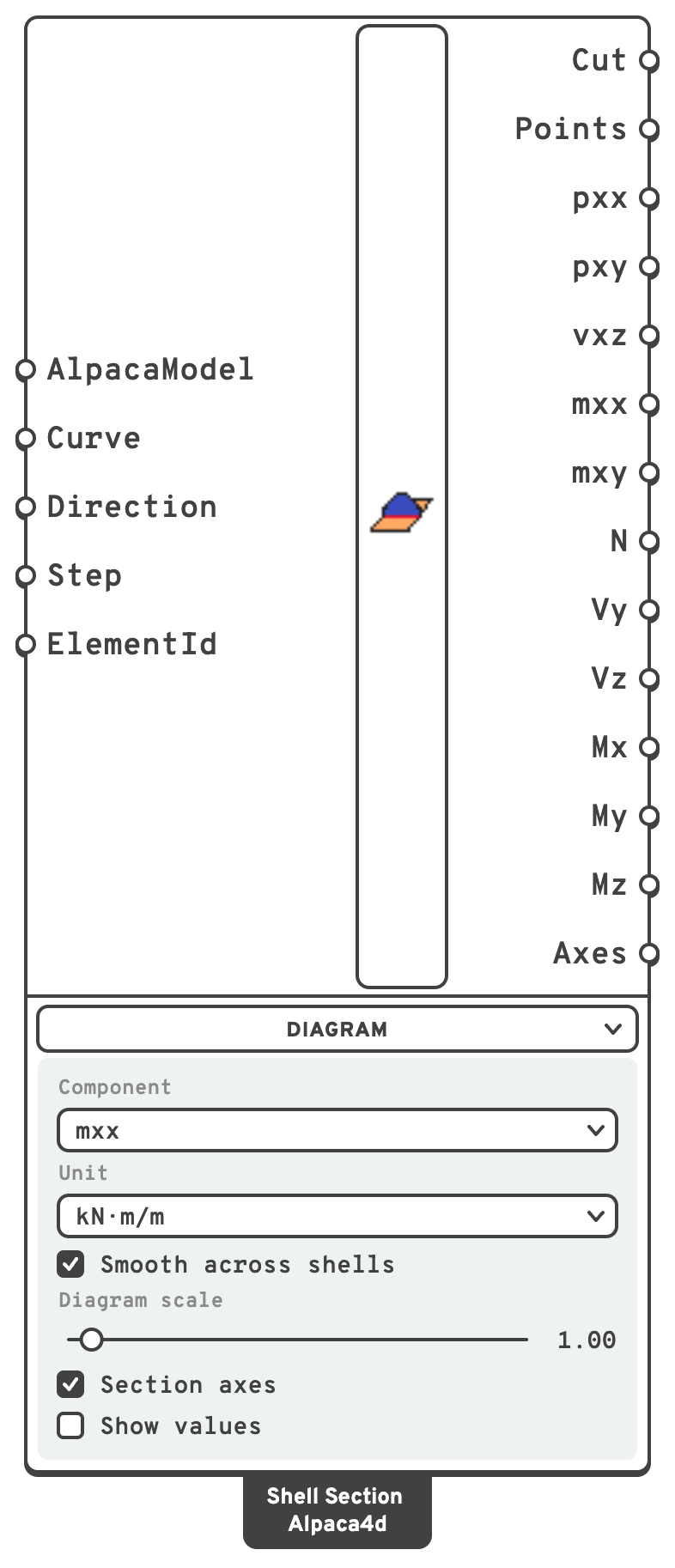
AlpacaModelThe analysed model, from Run Analysis.
CurveWhere to cut: a line or polyline drawn on the shells, or beside them to be swept onto them along Direction.
DirectionWhich way to sweep the curve to meet the shells.
ElementIdCut only some shells: an ElementId (Slab_3), a wildcard over them (Slab*), an element tag (47) or a regular expression (regex:^Wall).
The totals have one value per curve, in the branch the curves come from: two curves in {0} give two values of N in {0}. The per-length outputs have a branch per unbroken stretch of each curve, under it: the stretches of the second curve go in {0;1;0}, {0;1;1} and so on.
PointsWhere the forces are read: both ends and the middle of the cut through each shell.
pxxMembrane force across the cut, along x, in kN/m.
kN/m.kN/m.mxxBending moment whose stresses run across the cut, in kN·m/m.
kN·m/m.NTotal force across the cut, along x, in kN.
kN.kN.kN·m.MyBending about y, the shells bent out of their plane, as a slab is, in kN·m.
MzBending about z, the shells bent in their plane, as a wall is, in kN·m.
The outputs are in the units the model is solved in. The Unit of the menu sets only the values written in the viewport.
Diagram menu
What to draw. The menu starts open.
| Control | Default | Does | Shown |
|---|---|---|---|
| Component | mxx | The component the diagram shows: pxx, pxy, vxz, mxx or mxy. | Always |
| Unit | kN/m, kN·m/m | The unit the values are written in: N/m, kN/m, MN/m for the forces, N·m/m, kN·m/m, MN·m/m for the moments. | The one of the component |
| Smooth across shells | on | Reads the forces from a field smoothed across the shells. See Smoothing. | Always |
| Diagram scale | 1, from 0 to 20 | Stretches the diagram. At 1 the largest value stands off the cut 8 % of the model's diagonal, as Model View's beam diagrams do. One scale serves every curve. | Always |
| Section axes | on | Draws x, y and z at the centre of each cut, in red, green and blue. | Always |
| Show values | off | Writes the largest and the smallest value of each stretch at the tip of the diagram. | Always |
| Value text size | 0.5, from 0.05 to 5 | The height of those values, in model units. | With Show values on |
The diagram stands off the cut along the shells' normal, coloured by its sign in the colours of the beam force diagrams: a moment in those of My, a membrane force in those of N. A bending moment is drawn on the side it puts in tension.
✂️ How the cut is made
The curve is swept both ways along Direction, and the shells are cut where the swept surface crosses them.
- On the shells. Draw the curve on a slab or a wall and leave Direction empty: it is swept square to the shell, and the cut is the curve itself.
- In plan. Draw a line above a building and sweep it down (
0,0,-1): every wall it crosses is cut from top to bottom, and every slab along the line. - Some shells only. A line swept through a stack of floors cuts them all. Give ElementId to cut only the ones you mean.
A cut can cross shells in several places, through a slab with an opening or across two floors. Each unbroken stretch has a branch of its own, and the totals add up all of them.
💡 Sign convention
The cut has axes of its own, drawn when Section axes is on:
- x is square to the cut, in the shells' plane, to the left of the curve looking along Direction;
- y runs along the curve;
- z is the shells' normal, on the side Direction points to.
The forces are those the side x points to puts on the other side. Reverse the curve, or Direction, to read them from the other side.
The per-length outputs are those of Shell Forces, read in axes turned so that x is square to the cut: pxx, pxy, vxz, mxx and mxy are the ones that act on the cut's face. The totals are read like Beam Forces for a beam whose axis is x, and whose section is the cut: N along it, Vy along the cut, Vz square to the shells, and the moments about the centre of the cut.
Which way z points comes from Direction, not from the elements, so a mesh whose faces do not all face one way gives the same answer. With Direction empty it is the nearest shell's own local z, so mxx has the sign it has in Shell Forces there.
For example:
- A cantilever slab of mesh faces facing up, cut across with no Direction: z is up and x points to the tip. The tip pulls down and the slab hogs, so
Vzis minus the load on the tip andMyis plus its moment, top in tension. Swept down instead,Myis negative, still top in tension, because +z is now the bottom. - A wall cut along its length, swept square to it: x points up, so
Nis minus the weight above the cut,Vythe horizontal load above it, andMzthat load's moment about the centre of the cut.
Smoothing
An ASD Shell quad gives a single bending moment over the whole element, the value at its centre. Read unsmoothed, a moment that varies along the cut is drawn as steps, one per element, and where two elements meet the point is listed twice, once with each one's value.
With Smooth across shells on, the default, each corner of a shell takes the mean of the shells that meet there and lie within 30° of its plane, and the forces vary smoothly between the corners. A moment that varies linearly is then read exactly in the middle of a slab. At a support or a free edge there is only one side to take the mean of, so the value there is the element's own.
Along a line of the mesh, unsmoothed, the cut reads the elements on the side x points to.
Note
The totals are as good as the mesh. A displacement model is not in equilibrium point by point, so the totals of a cut add up to the loads only as closely as the mesh allows: exactly for a field the elements hold exactly, to a few per cent on a coarse mesh with the edge effects of a plate.
Triangles are as good as quads for the moments, and rough for the transverse shears. The shears an ASD Shell triangle records are scaled back by Shell Section to the ones it is in equilibrium with. They still differ by about a quarter from one point of an element to the next. Use quads where Vz matters.
📈 When to use it
Use it when
- You want the moment across a design strip of a slab: cut across the strip and read
My. - You want the forces at the base of a shear wall, or of a core:
N,VyandMz. - You want the shear along a support line, or the forces through a joint between two parts.
- You want to check equilibrium: a cut around a free part carries what is on it.
Do not use it when
- You want the forces of every element → Shell Forces.
- You want a contour over the shells → Model View, with Shell forces ticked.