Principal Stress Lines
Traces streamlines that follow the principal stress directions: across a shell, or through the inside of a solid. Where a contour shows how much, these show which way — the load paths through a plate, a block, a bone or a node.
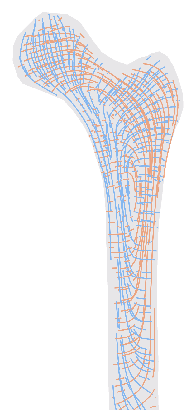
The Standardised Femur under the hip's force, in ten node tetrahedra: compression (SL3, blue) runs from the head down the inner side of the shaft, tension (SL1, orange) arches over the neck and down the outer side. The lines of a slice 1 cm thick through the middle of the bone.
🔧 Grasshopper component
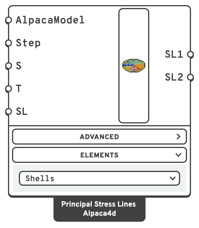
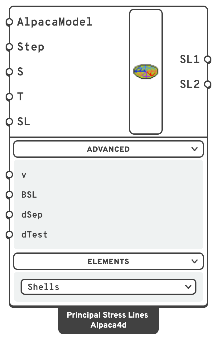
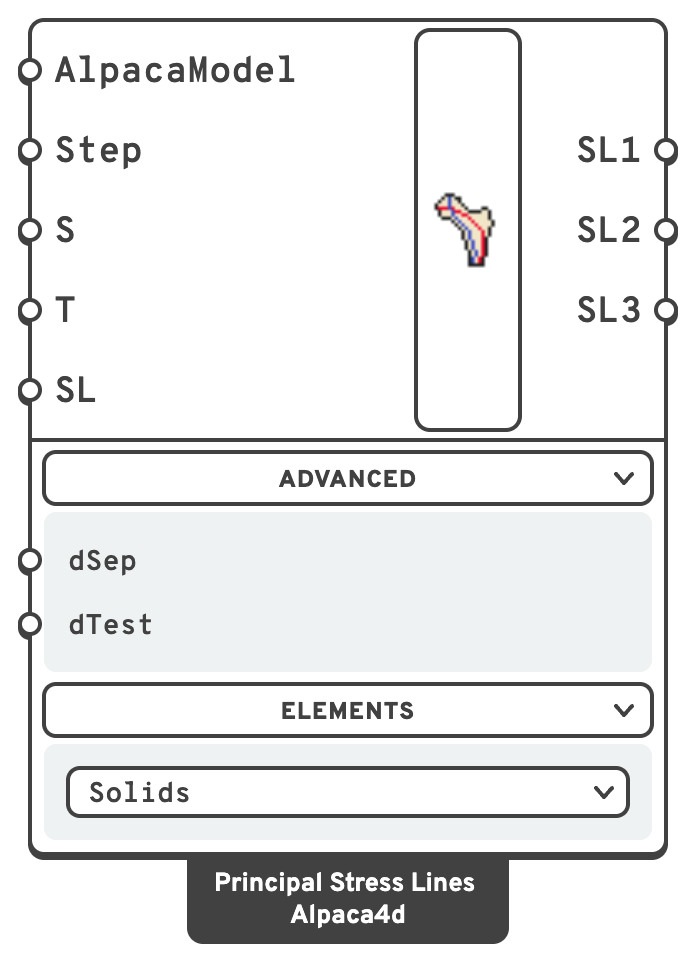
TStep ToleranceIntegration step along a line.
0 takes a third of the shells' mean edge length, so the default suits the model's units. Smaller is smoother and slower.true traces one line through the seed; false grows a field of lines from it.BSLBending Stress Linestrue uses rotations, giving the bending principal directions; false uses in-plane displacements, giving the membrane ones.
dSepSeparationTarget spacing between neighbouring lines, in field mode.
0 takes twice the shells' mean edge length.dTestTest Dist.A new line stops when it comes closer than this to an existing one.
0 disables the check.The last four — Poisson's ratio, Bending Stress Lines, Separation and Test Dist. — are in the Advanced menu under the component, which starts folded; click it to show them. A wire to one of them keeps working with the menu folded.
SSeedPoints inside the solid for the lines to go through.
TStep ToleranceLength of one step along a line.
0 takes a third of the elements' mean edge length.true draws one line of each family through each seed; false grows a field of lines from the seeds.dSepSeparationDistance between neighbouring lines in a field.
0 takes three times the elements' mean edge length.dTestTest Dist.In a field, a line stops when it comes closer than this to one already drawn.
0 lets lines run on.On Solids, the last two — Separation and Test Dist. — are in the Advanced menu.
With Single Line on, each output has one line per seed, in the order of the seeds: an empty one where the seed is off the shells or outside the solid, or the stress there gives no direction.
Pick what the lines run in from the Elements drop-down on the component:
- Shells draws lines over shell elements, along the two principal directions in each shell's plane — of the membrane stress, or of the bending moment. It is where the component starts, and where files from before Solids open.
- Solids draws lines through the inside of SSP Bricks and tetrahedra, along all three principal stresses.
Each has inputs of its own, below. They share the first two outputs, SL1 and SL2, and Solids adds a third, SL3. Switching keeps the wires on SL1 and SL2.
📈 When to use it
Use it when
- You are laying out reinforcement in a slab or a wall and want the bars to follow the force.
- You are looking for the load path through a plate — where the arching, the fan, the strut actually goes.
- You are working out where to place ribs, stiffeners, or the members of a discrete structure that replaces the shell.
- You want to see how a load travels through a solid: a footing, a corbel, a node, a bone.
- You are shaping a solid by its load paths — where to keep material, where a strut or a tie runs — before Topology Optimisation or instead of it.
Do not use it when
- You need a magnitude → Model View, Shell Forces or Brick Stresses.
🧮 How the lines are made
On shells
Each shell's strain is taken at its centre: the membrane strain from the nodal translations, or the bending curvature from the nodal rotations. The centre values are averaged into each node from the shells round it that lie within 30° of each other, and interpolated across each shell, so the directions run on smoothly from shell to shell. Shells are joined through the nodes they share, exactly as Assemble Model welded them.
- Material. For an isotropic elastic material the principal stresses lie along the principal strains, so the strain gives the directions. On a layered or nonlinear section the lines follow the strain, which is no longer the same as the stress.
- Bending. Each shell's bending is read against its normal. Shells that face the other way from their neighbours are read the other way up, so that the lines run on across them, and a Remark says how many there were.
- Where a line ends. At the edge of the shells, cut where it crosses. Also where the two principal values become equal, as at the centre of a square slab or the middle of a simply supported edge, because there the field gives no direction to follow.
The method follows LilyPad, by Matthew Church and Format Engineers: lines traced with fourth-order Runge-Kutta steps, and a field of them grown by neighbour seeding. Checked against closed-form solutions (the Timoshenko cantilever, a plate with a hole in tension, and a simply supported plate under uniform load), the lines follow the exact directions to within half a degree on average, on meshes as coarse as eight shells across a beam's depth.
Through solids
The stress comes from the solver, element by element: one value for an SSP Brick, which integrates at a single point, and one at each node for a Ten Node Tetrahedron, whose stress is linear. Each node takes the volume-weighted mean of what the elements round it give it, so the field runs on smoothly from element to element.
Every element is then cut into tetrahedra on points it shares with its neighbours — a ten node tetrahedron into eight, a brick into twenty-four round its centre and the centres of its faces — and each tetrahedron knows the one across each of its faces. A line is traced in fourth-order Runge-Kutta steps. At each step the stress is interpolated in the tetrahedron the point is in, found by walking from the one it was in before, across the face it has crossed, and split into its three principal stresses and their directions. A face no other tetrahedron shares is the solid's surface.
- Where a line ends. At the surface of the solid, cut where it crosses. Also where its principal stress becomes equal to another — in a solid that happens along whole lines, such as an axis of symmetry — because there the stress gives no direction to follow.
- Elements. A Ten Node Tetrahedron gives its stress at its nodes and follows a smooth field closely. An SSP Brick gives one stress, at its centre: averaged into the nodes, it is half an element out at the surface of the solid, so a brick model wants a finer mesh near the surface for the same accuracy.
- Material. The lines follow the stress the solver reports, whatever the material.
Checked against closed-form solutions — a round bar twisted and pulled, whose lines are helices round its axis and rays out from it, Boussinesq's point load on a half-space, and Timoshenko and Goodier's cantilever and simply supported beam — on models OpenSees solved, the lines follow the exact directions to within 0.1–0.6° on average, on Ten Node Tetrahedra and on SSP Bricks alike. A beam held and loaded as it would be drawn, clamped or on its bottom edges, follows them as closely more than a depth away from its supports and loads.
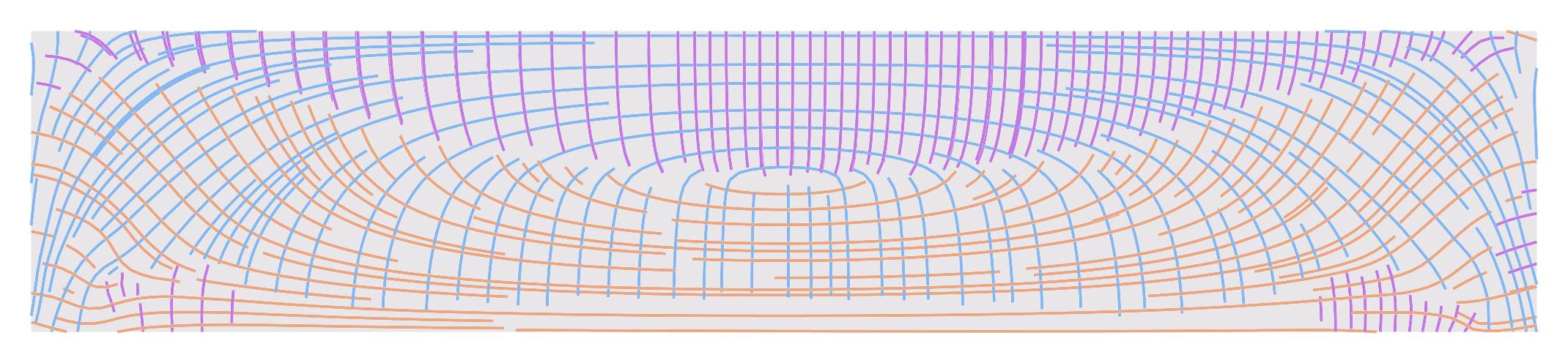
A simply supported beam of Ten Node Tetrahedra under a uniform load, seen from the front: tension (SL1, orange) sags along the bottom and rises to the supports, compression (SL3, blue) arches between them. In the top, where both stresses in the beam's plane are compressions, the largest principal stress is the one across the width, nought, and the second family of the familiar two-dimensional picture is SL2 (purple).
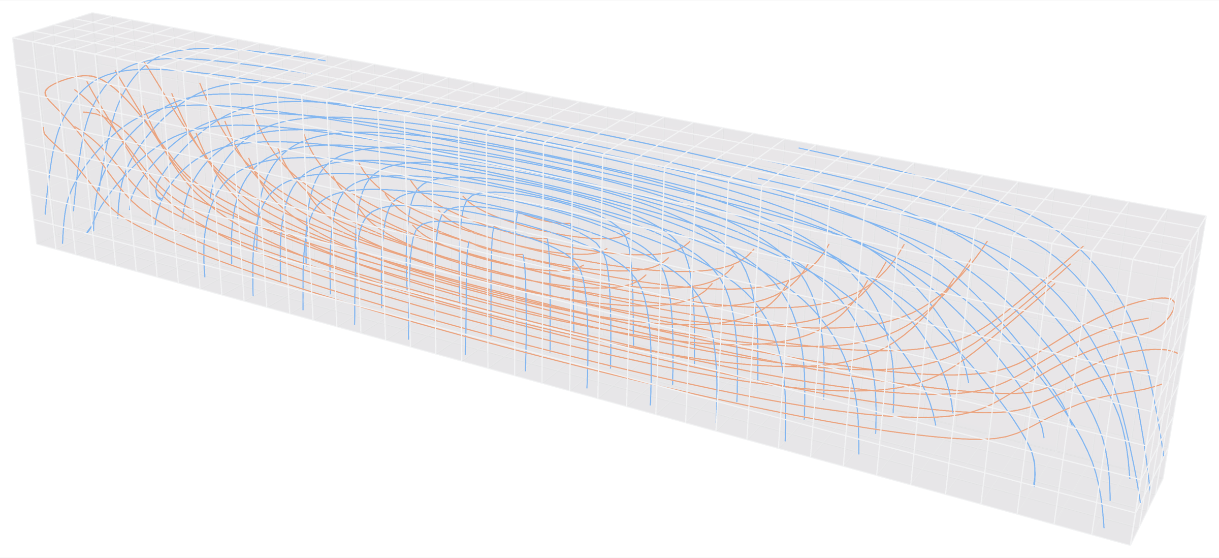
A simply supported beam of 1,280 SSP Bricks, 10 m long, 2 m deep and 1 m wide, under a uniform load on its top: one line of each family through points every 0.5 m along the neutral axis, at the back, the middle and the front of the width. Tension (SL1, orange) sags along the bottom and rises to the supports; compression (SL3, blue) arches between them and, below the neutral axis, runs straight down until the vertical stress fades to nothing.
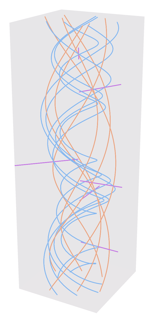
A bar twisted and pulled, in Ten Node Tetrahedra: the tension (orange) and compression (blue) lines are helices winding opposite ways round the axis; the middle principal stress (purple) points straight out from it.
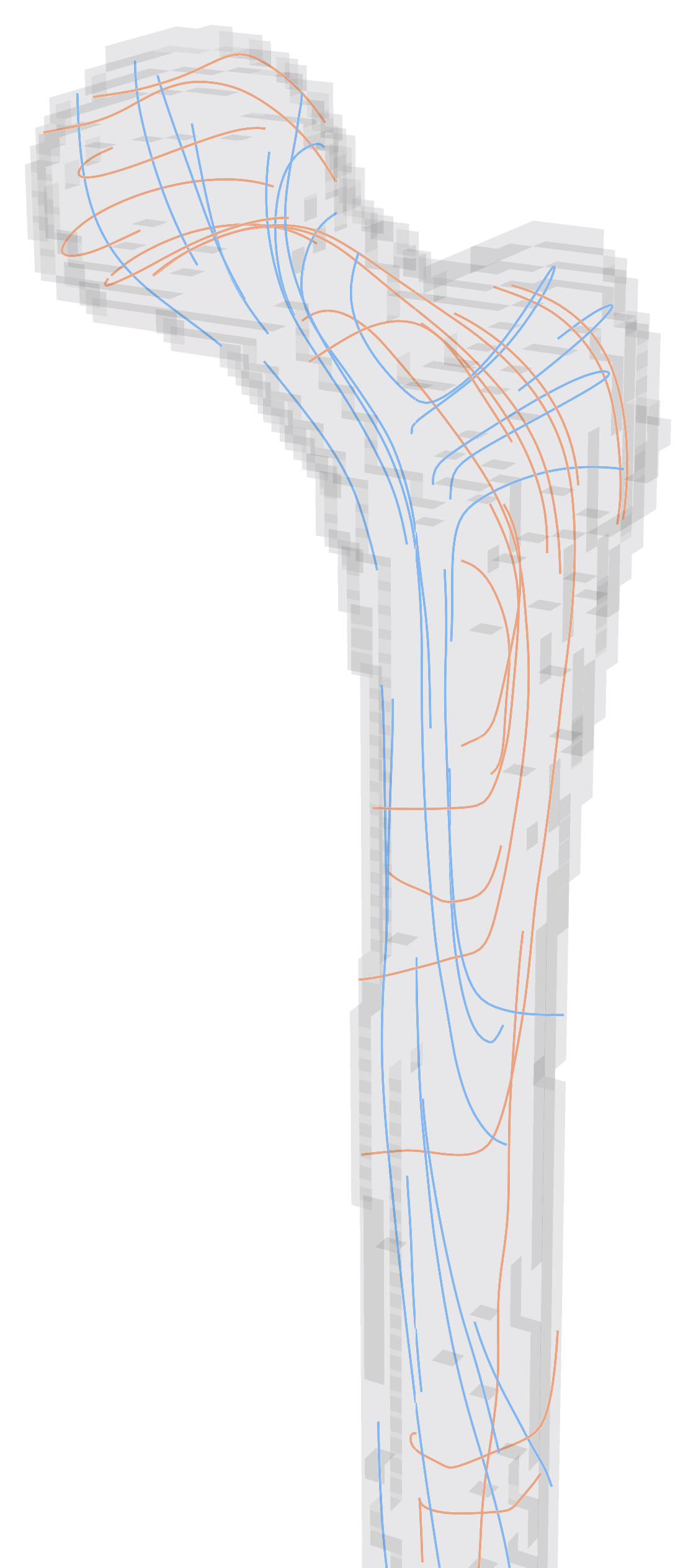
The femur again, in 9,960 SSP Bricks of 3.5 mm: a field of lines grown from seeds in the bone's middle plane, through the whole bone and seen in perspective. Compression (SL3, blue) runs down the head and the inner side of the shaft, tension (SL1, orange) over the neck and down the outer side, as in the slice through the tetrahedra above. The steps of the outline are the bricks; lines shorter than 3 cm are left out.
💡 Tuning it
Start with one seed and Single Line on, to check the direction field is sensible. Then turn it off and adjust:
- Separation controls how dense the field is.
- Test Dist., once non-zero, stops lines crowding — set it a little below Separation.
- Step Tolerance smooths each line. Left at
0it follows the mesh; reduce it if the curves look faceted, at some cost in time.
Set Bending Stress Lines to match the problem: membrane directions for a wall in its own plane, bending directions for a slab in flexure. They are generally not the same field.
On Solids, start with a few seeds and Single Line on, to see the three families. Then:
- Where two principal stresses are close, their two families wander: the direction turns on a difference the mesh cannot resolve. Under a point load on a block, for example, the two horizontal stresses stay within a percent of each other below the load, and only the vertical compression gives clean lines. Look at the family whose stress stands well apart from the others.
- A field (Single Line off) fills the whole solid, and the lines hide one another. Seed it from points in one region, keep Separation generous, and set Test Dist. to about half of it. A field stops at 5000 lines.
- Step Tolerance smooths each line. Left at
0it follows the mesh.