Beam Forces
Internal forces along every beam element — the axial force, two shears, torsion and two bending moments.
🔧 Grasshopper component
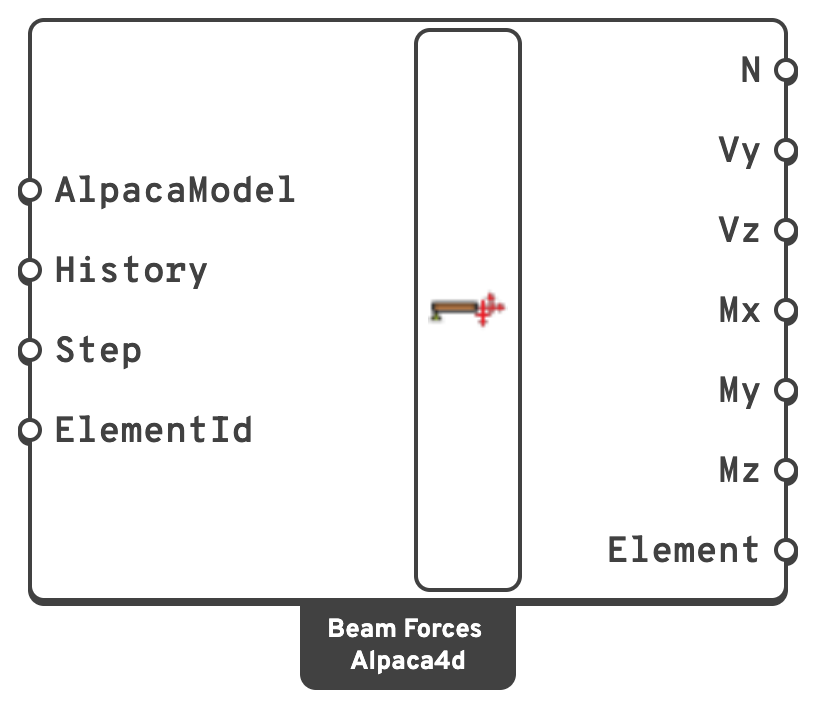
HistoryRead every recorded step instead of one.
{step; element}. Step is ignored.ElementIdRead only some of the beams: an ElementId, a wildcard over them, a tag, or a regular expression.
The six forces are data trees, one branch per beam element, keyed by its tag. Within a branch, the values are at the element's integration points, ordered from the I end to the J end.
kN. Positive is tension.VyShear along the local y axis, in kN.
VzShear along the local z axis, in kN.
MxTorsion about the local x axis, in kN·m.
MyBending about the local y axis, in kN·m.
MzBending about the local z axis, in kN·m.
ElementThe beams read, in the order of the branches.
📈 When to use it
Use it when
- You need design forces — the numbers that go into a code check.
- You want the maximum moment in a member: take the branch and find its extreme.
- You are exporting to a spreadsheet or a downstream design tool.
Do not use it when
- You want to see the diagram → Model View, with Beam forces ticked, draws any of the six in the viewport, as many at once as are ticked in its row.
Warning
The resolution is the element discretisation. Forces are sampled at the integration points of each element — five per element, Newton–Cotes. A single element spanning a whole beam gives you five points, and the peak moment will be missed unless it happens to fall on one of them.
This is the same reason Gravity Load asks you to split beams. Five or more elements per span is a reasonable default.
💡 Local axes
My and Mz are about the element's local axes, set by the ZAxis input of the ForceBeamColumn component. Turn on Local Axes in Model View if you are unsure which way round they are on a given member — it is the most common source of a moment that looks like it is about the wrong axis.
➕ Signs
The forces are signed as OpenSees reports them, in the element's local axes: x runs from the I end (the start of the line) to the J end, and y and z are the ones Local Axes draws in Model View. Left without a ZAxis, a beam has y pointing up and z horizontal.
| Force | Positive when | Stress it causes |
|---|---|---|
| N | the member is in tension | σ = N / A |
| Mz | the +y side is in compression — sagging, on a beam with y up | σ = −Mz · y / Iz |
| My | the +z side is in tension | σ = +My · z / Iy |
| Vy | Vy = dMz/dx: a cantilever fixed at I and loaded at J towards −y | |
| Vz | Vz = dMy/dx: a cantilever fixed at I and loaded at J towards +z | |
| Mx | a torque about +x is applied at the J end (right-hand rule) |
The two shears do not follow the same rule. That is OpenSees's convention, not a slip: it defines each shear as the slope of the moment it goes with, and Mz and My take opposite signs for the same curvature. Beam Stresses and Utilisation use these signs as they are.
💡 Sections without shear
A Generic Section with AlphaY or AlphaZ of 0 is rigid in shear, and OpenSees records only N, Mz, My and Mx along a beam made of it. Vy and Vz are then worked out as the slopes of Mz and My along the beam. That is exact for the loads Alpaca4d puts on beams: under a uniform load the moments are quadratic along the beam.