Utilisation
Checks every beam against the design code of its material and reports how much of each resistance it uses: 1 is exactly at the limit. Steel is checked to EN 1993-1-1 (Eurocode 3) — cross-section resistance, flexural buckling, lateral-torsional buckling and bending with compression as a member.
🔧 Grasshopper component
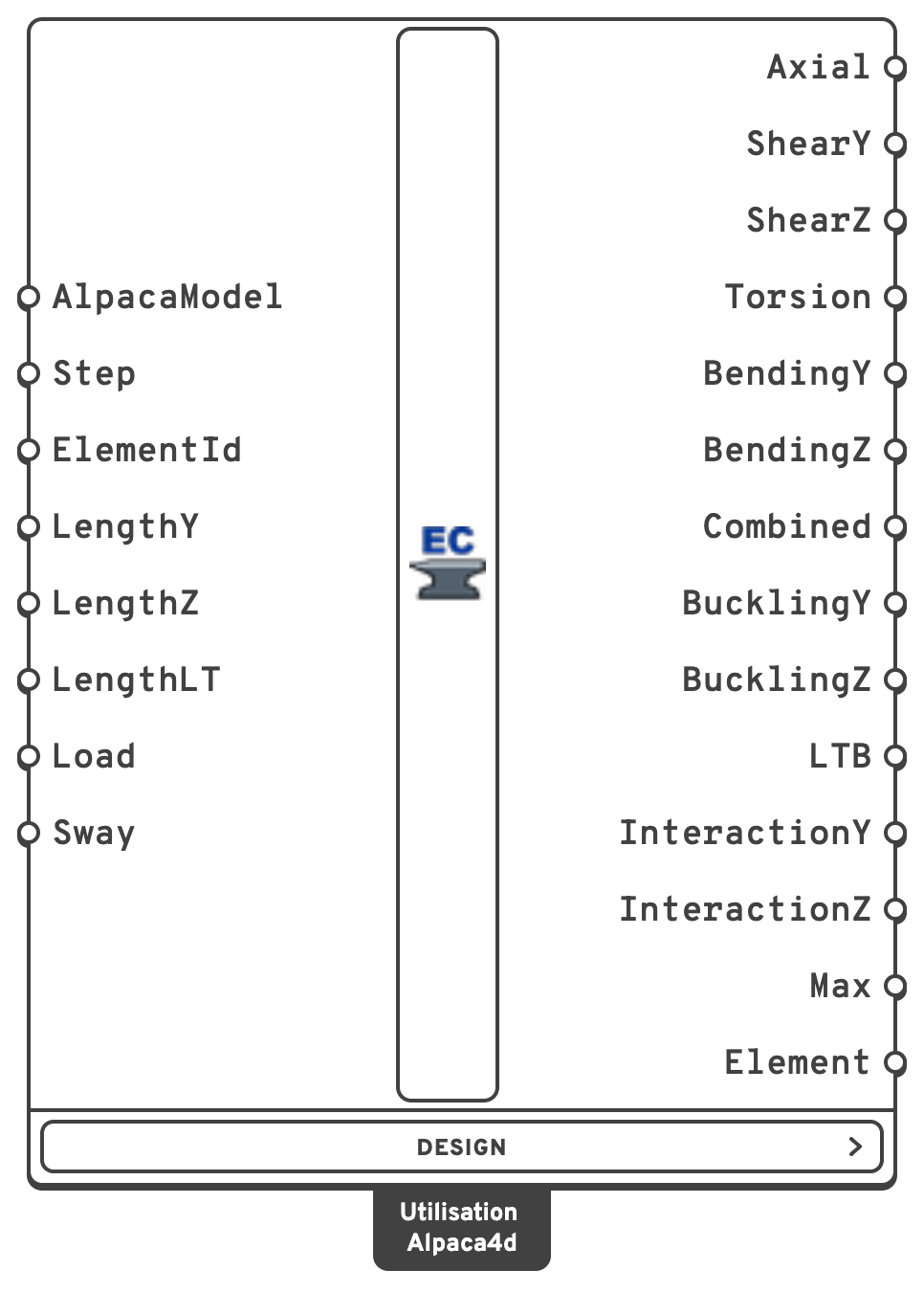
ElementIdCheck only some of the beams: an ElementId, a wildcard over them, a tag, or a regular expression.
LengthYBuckling length L_cr about local y — the minor axis of an I — in m.
LengthZBuckling length L_cr about local z — the major axis of an I.
LengthLTDistance between lateral restraints, for lateral-torsional buckling, in m — see Lateral-torsional buckling below.
ShearCentre, Destabilising (or Top) — on the face it comes from, gravity on the top flange — or Stabilising (or Bottom), hung from the face it goes towards.Warning
Lengths left empty are each beam's own length, held at both ends. A member drawn as several beams needs its whole length given — each beam's own is only a piece of it — and so do a sway column and a cantilever, whose free tip is not held at all.
One item per beam, in the order of the Element output. A check that could not be made is empty, never zero.
ShearYVy against the plastic shear resistance, reduced for torsion (6.2.6, 6.2.7).
ShearZVz against the plastic shear resistance, reduced for torsion.
BucklingYFlexural buckling about local y — the minor axis of an I (6.3.1).
LTBLateral-torsional buckling (6.3.2): the major axis moment against χLT·W·fy/γM1, the worst piece between lateral restraints.
InteractionYBending and axial compression as a member (6.3.3, Annex B): the one of (6.61) and (6.62) whose χ is about local y — (6.62) for an I.
MaxThe largest of the above.
Design menu
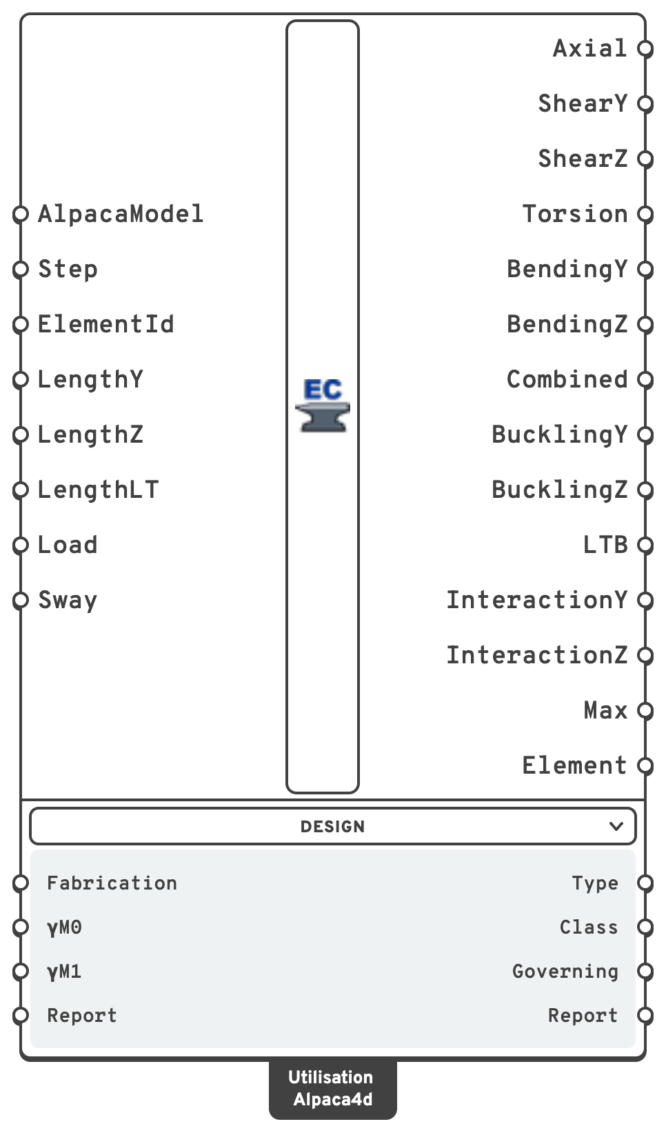
Below the component, folded away until you open it. Its inputs are set once per project and then left alone; its outputs say more about a beam than how loaded it is.
| Input | Nick | Type | Default | Description |
|---|---|---|---|---|
| Fabrication | Fabrication | Text | Rolled | Rolled — rolled I-sections and hot-finished hollow sections. Welded — welded I-sections and cold-formed hollow sections. Sets the buckling curves and an I's shear area. |
| γM0 | γM0 | Number | 1.0 | Partial factor for the resistance of cross-sections. A National Annex may set another value. |
| γM1 | γM1 | Number | 1.0 | Partial factor for the resistance of members to instability. A National Annex may set another value. |
| Report | Report | Boolean | false | Write the Report output. Off by default: on a large model the text is most of the work, and off, none of it is written. |
| Output | Nick | Type | Description |
|---|---|---|---|
| Type | Type | Text (list) | What the beam is made of, from its material: Steel, or Unknown when the material has no design grade. |
| Class | Class | Integer (list) | Cross-section class, 1 to 4, the worst along the beam. |
| Governing | Governing | Text (list) | Which check gives Max, or which checks could not be made. |
| Report | Report | Text (list) | Everything worked out on the way — grade, fy, class, section properties, resistances, where each check governs and what is not covered. Put it in a panel to check a member by hand. Empty unless the Report input is on. |
Careful
Not checked yet: torsional and torsional-flexural buckling (6.3.1.4) — which can govern a pair of angles in compression — warping torsion, shear buckling of slender webs (EN 1993-1-5) and Class 4 sections. 6.3.3 is for doubly symmetric sections only: an I with unequal flanges or a pair of angles in compression and bending gets no interaction, and no Max.
Frame stability is the model's: the forces are the analysis's, with whatever second-order effects and imperfections it includes.
💡 Where the steel grade comes from
From the beam's material. Make it with Material Database, which stamps the grade on it, or give a Uniaxial material the name of its grade: S355, S355JR, s355 j2 and S 355 are all S355. A material with any other name is Unknown and is left unchecked, with a warning.
fy follows EN 1993-1-1 Table 3.1 for the section's thickest plate, including the lower value for plates thicker than 40 mm:
| Grade | t ≤ 40 mm | 40 < t ≤ 80 mm |
|---|---|---|
| S235 | 235 | 215 |
| S275 | 275 | 255 |
| S355 | 355 | 335 |
| S450 | 440 | 410 |
💡 Axes
Alpaca4d's local axes, as in Beam Forces: local y along the depth of the section as drawn, local z across it. For an I that makes bending about z the major axis — EN 1993-1-1's y-y — and ShearY the shear along the web. So BendingZ and BucklingZ are the major axis of an I, BendingY and BucklingY the minor.
💡 What is checked
| Check | Clause | How |
|---|---|---|
| Class | 5.5, Table 5.2 | Every flange, web and wall, for the stress it carries at each integration point |
| Axial | 6.2.3, 6.2.4 | N / (A fy/γM0) |
| Shear | 6.2.6, 6.2.7(9) | V / (Av fy/√3/γM0), the shear area from 6.2.6(3), reduced for the torsional shear stress |
| Torsion | 6.2.7 | τt / (fy/√3/γM0), St. Venant — the only torsion the analysis has |
| Bending | 6.2.5, 6.2.8 | M / (W fy/γM0): Wpl for Class 1 and 2, Wel for Class 3. Past half the shear resistance, fy is reduced over the shear area — (6.30) for an I |
| Combined | 6.2.9, 6.2.10 | Class 1 and 2: the reduced plastic moments M_N,Rd and the biaxial criterion (6.41), with the exponents of the shape. Class 3: the largest direct stress against fy/γM0 |
| Buckling | 6.3.1 | N / (χ A fy/γM1) about each axis, for the largest compression along the beam, with the buckling curve of Table 6.2 |
| LTB | 6.3.2 | M / (χLT W fy/γM1) for every piece between lateral restraints, M_cr from the beam's own moment diagram — see below |
| Interaction | 6.3.3, Annex B | (6.61) and (6.62) with the interaction factors of Annex B (method 2), the largest N and M along the beam |
Every cross-section check is made at every integration point — five along a beam — and the worst is reported; the Report says where.
The reduced plastic moments by shape:
| Section | M_N,Rd | Exponents in (6.41) |
|---|---|---|
| I Section, equal flanges | (6.36) to (6.38) | 2 on Mz, 5n ≥ 1 on My |
| Rectangular Hollow, uniform walls | (6.39), (6.40) | 1.66 / (1 − 1.13n²) ≤ 6 |
| Circular, tube or bar | M_pl (1 − n^1.7) | 2 |
| Rectangular | M_pl (1 − n²) | 1 |
| Unequal I, uneven box, Double L-Angle | none given | the linear sum of 6.2.1(7) |
Note
Combined is reported as the largest of each moment over its reduced resistance and the left-hand side of (6.41). It is ≤ 1 exactly when (6.41) holds — but where (6.41) alone would turn a member at 90% of its reduced moment into 0.81 (an exponent of 2), this reads 0.9. Some tools report the left-hand side alone, so their number can be lower for the same member.
💡 Buckling curves
Table 6.2, from the shape and Fabrication — Rolled picks the rolled I and hot-finished rows, Welded the welded I and cold-formed ones:
| Section | Major axis | Minor axis |
|---|---|---|
| Rolled I, h/b > 1.2, tf ≤ 40 mm | a | b |
| Rolled I, h/b > 1.2, 40 < tf ≤ 100 mm | b | c |
| Rolled I, h/b ≤ 1.2, tf ≤ 100 mm | b | c |
| Rolled I, h/b ≤ 1.2, tf > 100 mm | d | d |
| Welded I, tf ≤ 40 mm | b | c |
| Welded I, tf > 40 mm | c | d |
| Hollow, rectangular or circular, hot finished | a | a |
| Hollow, cold formed | c | c |
| Solid bar, rectangular or round | c | c |
| Double L-Angle | b | b |
From fy = 460 N/mm² the rolled I and hot-finished rows take Table 6.2's S460 column instead — a0, a or c. An I with unequal flanges takes the welded rows whatever Fabrication says — nobody rolls one.
Buckling may be ignored where λ̄ ≤ 0.2 or N_Ed ≤ 0.04 N_cr (6.3.1.2(4)); the check then reads the cross-section's compression at γM1.
💡 Lateral-torsional buckling
M_cr is worked out on the moment diagram each beam actually carries, rather than read from tables of C1 and C2: the classical energy solution LTBeam uses, with the beam's lateral deflection and twist as sine series. EN 1993-1-1 gives no formula for M_cr and asks only that it allow for the loading, the moment distribution and the restraints, which this does. Between its nodes a beam under a uniform load carries a parabola, so the diagram through the integration points is exact. The Report gives the C1 it amounts to.
- Restraints. Each beam is held sideways and against twist at both ends and at equal steps no longer than LengthLT in between, and is free to rotate and warp at each of them — fork supports, k = kw = 1. Each piece is checked on its own part of the diagram.
- Longer than the beam, LengthLT stands for an unrestrained length the beam is only part of, or for a cantilever's effective length. The rest of that length's diagram cannot be known from this beam, so its peak moment is taken as uniform over all of it — the most severe distribution.
- Load height.
Destabilisingputs the load on the extreme fibre it comes from,Stabilisingon the one it goes towards; which face that is follows from the direction of the load along the beam. - Monosymmetric sections — an I with unequal flanges, a pair of angles — include the Wagner term, with the shear centre where it is.
- χLT by 6.3.2.3 for a rolled or equivalent welded I, with the recommended λ̄LT,0 = 0.4 and β = 0.75 and curves b to d of Table 6.5, without the modification f of 6.3.2.3(2) — a National Annex may allow it, and leaving it out is the safe side. Everything else by the general case 6.3.2.2, curve d for anything but an I.
- Lateral-torsional buckling may be ignored where λ̄LT ≤ λ̄LT,0 or M_Ed ≤ λ̄LT,0² M_cr (6.3.2.2(4)); LTB then reads the cross-section at γM1. 6.3.3 takes χLT from the curve all the same: compression lowers the moment a beam buckles at.
A tube or a round bar is the same about every axis and cannot buckle sideways. A box can, if it is long and narrow enough.
💡 Bending and compression (6.3.3)
(6.61) and (6.62), the standard's y being the major axis, with Annex B's interaction factors — Table B.2 for open sections, which can twist, Table B.1 for boxes and tubes. Cm comes from Table B.3 on each beam's own diagram — unless its buckling length about that axis is longer than the beam, when the diagram that matters is not the beam's and Cm = 1, or unless Sway is on, when it is 0.9. CmLT is that of the piece between restraints with the lowest χLT.
Both are reported for every beam with compression and bending, and for a beam bent about both axes without compression — the only rule EN 1993-1-1 has that puts lateral-torsional buckling and minor axis bending together.
⚠️ Class 4, and checks that could not be made
Class 3 at low stress. A part that fails the Class 3 limit is given the second chance of 5.5.2(9): it is Class 3 after all if it meets the limit with ε raised by √(fy/γM0 / σcom,Ed), σcom,Ed the compression it actually carries. Without it, every point of a slender I where the moment passes through zero would read as Class 4 under the slightest axial force — the web of an IPE 300 in S355 is Class 4 in pure compression. Such a section is checked elastically, and the component says so with a remark.
Class 4. A section still Class 4 after that needs the effective properties of EN 1993-1-5, which are not worked out yet. The beam is not checked at all — its outputs are empty — and the component warns.
Class 4 for buckling only. 5.5.2(10) forbids the second chance for member buckling, which is classified by Table 5.2 alone. A beam whose section is Class 4 in compression gets its cross-section checks, but its buckling is not checked unless N_Ed ≤ 0.04 N_cr — and then Max is empty and Governing reads Not checked: BucklingY, BucklingZ. A largest value over the checks that were made would read as a verdict on the beam, and it is not one.
The component's messages:
| Message | Level | Means |
|---|---|---|
| ... have a material with no design grade and are not checked | Warning | Type is Unknown. Give the material a grade. |
| ... are Class 4 and are not checked at all | Warning | The section is Class 4 even at the stress it carries. Outputs empty. |
| ... are Class 4 by Table 5.2 alone, so their member checks are not made and Max is empty | Warning | Cross-section checked; buckling, LTB and 6.3.3 not. |
| ... are not doubly symmetric ... 6.3.3 covers doubly symmetric members only | Warning | An unequal I or a pair of angles in compression and bending: no interaction, no Max. |
| ... use a section with no shape | Warning | A Generic Section: no plates to check. |
| ... have checks that could not be made, so no Max | Warning | Anything else missing — see the Report. |
| ... taken as Class 3 under 5.5.2(9) | Remark | Checked, elastically, at the low stress the part carries. |
| Buckling lengths left empty are each beam's own length | Remark | A lengths input is empty; give lengths for members drawn as several beams, sway columns and cantilevers. |
💡 Sharp corners
The check uses the section the analysis used. An I Section — including the Steel Section Library profiles — has no root radius, and a hollow section no corner radius. Against a rolled catalogue section that makes A and Wpl a few percent low (an IPE 300's Wpl,y is 602 cm³ against the catalogue's 628) and a web's c/t a little high: all on the safe side. Box walls are classified on their flat width h − 3t, as the section tables do for hot-finished tubes.
📈 When to use it
Use it when
- You want to know whether steel members are big enough, and which check governs.
- You are sizing members: feed Max back into a section choice.
Do not use it when
- The member is a pair of angles or an unequal I in compression, where torsional-flexural buckling or 6.3.4 may govern → check those yourself; this component does not yet.
- You only want the stresses → Beam Stresses.
✅ How it is checked
The rules are set against published worked examples, each in its own units and to the digits printed:
| Source | Member | Checked |
|---|---|---|
| JRC 2014, Eurocodes — Design of steel buildings with worked examples, Example 1 | HEB 340 column, S355 | class, N_c,Rd, λ̄, curves, χ, N_b,Rd |
| ibid., Example 2 | IPE 400 beam, S355 | class, M_pl,Rd, V_pl,Rd, shear area, shear buckling limit |
| Gardner & Nethercot, Designers' Guide to EN 1993-1-1, Example 6.6 | UKB 457×191×98, S275 | class, N_pl,Rd, M_pl,Rd, M_N,y,Rd |
| ibid., Example 6.7 | CHS 244.5×10 column, S355 | end to end through Alpaca4d's own section: class, N_cr, λ̄, χ, N_b,Rd, utilisation 0.71 |
| Structville, Design of steel columns for biaxial bending | UKC 254×254×89, S275 | M_N,y,Rd, M_N,z,Rd, β, (6.41), χ |
| ECCS No. 119, Worked Example 5, as SOFiSTiK verification DCE-EN24 | IPE 500, S235, 3.75 m | M_cr,0 895 kNm, C1 1.194 of a −100 / 199 / −100 kNm diagram against SOFiSTiK's eigenvalue analysis, λ̄LT, χLT by 6.3.2.2 |
| Schneider, Bautabellen für Ingenieure, Example 8-41, as SOFiSTiK verification DCE-EN29 | HEA 200 beam-column, S235, 8 m held at mid-length | λ̄, χ, N_cr, λ̄LT, χLT by 6.3.2.3, Cmy, CmLT, kyy, kzy, (6.61) 0.96, (6.62) 0.79 — and end to end through Alpaca4d's own HEA 200 |
The critical moment is also held to the closed forms — uniform moment, doubly and singly symmetric — and to the C1 and C2 of ENV 1993-1-1 Annex F. Then every shape against hand formulas, members worked by hand, and the whole chain — a recorder file solved by OpenSees, read and checked.
Note
End to end, the Schneider column reads 1.00 for (6.61) against the book's 0.96: Alpaca4d's HEA 200 has no root radii, so its area is 5% low. M_cr comes out at 256 kNm against the book's 220.9, because the book's load-height term is DIN 18800's fixed 0.5 z_p whatever the diagram. Most of each half's moment comes from the reaction, not from the top-flange load. With the load at the shear centre the two agree: C1 1.336 against the book's ζ = 1.35.